Privacy statement: Your privacy is very important to Us. Our company promises not to disclose your personal information to any external company with out your explicit permission.
introduction
This article refers to the address: http://
Conformal array antennas are one of the most important development directions in current antenna technology. Microstrip antennas have been widely used in missiles, aircraft, satellites, rockets and other aircraft in recent years due to their low profile, small size, light weight and easy to conform to the carrier. However, microstrip array antennas are less efficient due to ohmic losses, dielectric losses, and spurious emissions in the feed network, especially when the frequency is high or the feed network is long. To solve these problems, a waveguide hybrid feed is introduced to reduce losses. A 40 GHz planar array antenna was designed by using waveguide longitudinal slot coupling feed. The E-plane lobes were asymmetrical due to the alternating arrangement of the coupling slits. The 30*30 planar array antenna was designed by tilt-coupled double-slit feed. The desired radiation causes the antenna gain to drop.
In this paper, a Ku-band microstrip conformal array antenna is designed by using the waveguide microstrip hybrid feed mode. The string feed microstrip line array is conformal to the cylindrical surface. The waveguide network is excited by the symmetric double-slit coupling to the microstrip line array. The adoption effectively suppresses the radiation of the coupling slit and improves the polarization purity of the antenna. The experimental results show that the antenna performance is excellent.
2 waveguide feeding microstrip conformal antenna
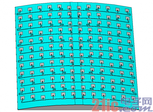
The waveguide-fed microstrip conformal antenna is shown in Figure 1. The array antenna comprises 12 1*12 microstrip line arrays, the microstrip line array adopts a rectangular patch radiating unit, and the microstrip line series feeds excitation, and the basic string feeding power dividing unit is shown in FIG. 2 .

Figure 1 Schematic diagram of a microstrip conformal antenna array

Figure 2 string feed splitter
Let 1 port be the input port, and the 2 and 3 port power ratios be
, there are:
According to the amplitude weighting coefficient of the microstrip line array, the power division ratio of each power divider is calculated to determine the microstrip cross-feeding power division network.
Since the microstrip line array is conformal to the cylindrical surface, the curvature of the cylinder causes a spatial path difference between the radiating elements, and the phase difference introduced by the space difference of the antenna unit is compensated by adjusting the length of the feeding microstrip line of each radiating element. In order to reduce the feed loss and improve the antenna efficiency, the waveguide network is used to couple the microstrip line array. The waveguide feed network consists of a T-joint and a series of longitudinal coupling slits on the broad side of the waveguide, as shown in Figure 3. The waveguide network terminal is short-circuited, and the distance between the coupling slits is 0.5.
, distance short-circuit surface 0.25
Form a standing wave array. The coupling joint adopts a symmetrical double-slit structure to ensure the structural symmetry of the antenna, effectively suppress the radiation of the coupling slit, and improve the polarization purity of the antenna.

Figure 3 Microstrip conformal antenna array perspective

Figure 4 Conformal microstrip array antenna
3 Experimental results
A 12*12 unit microstrip conformal array antenna was processed, and the antenna port standing wave and lobe pattern and gain test were performed respectively, as shown in Fig. 4. The test results show that the impedance bandwidth with a reflection coefficient of less than -10 dB is 700 MHz (see Figure 5). Figure 6 is a 15.3 GHz H-plane lobe diagram, that is, a cylindrical conformal surface lobe diagram, and Figure 7 is a cylinder axial direction, that is, a waveguide feed plane lobe diagram, the cross-polarization level is less than -25 dB, and the antenna gain is 27.9dB, radiation efficiency is 51%.

Figure 5 Antenna standing wave curve

Figure 6 Conformal antenna H surface lobe

Figure 7 Conformal antenna E-surface lobe
4 Conclusion
This paper introduces the design of Ku-band 12*12 waveguide-fed microstrip conformal array antenna. The conformal surface is microstrip line array fed by microstrip line series, and the waveguide network is used to feed the microstrip line array. The proposed symmetric double-slit coupling feed effectively suppresses the radiation of the coupling slot and improves the antenna efficiency and polarization purity. The test results show that the impedance bandwidth is 700MHz, the cross-polarization level is lower than -25dB, and the antenna efficiency is 51%.
November 16, 2024
September 18, 2023
June 28, 2024
June 28, 2024
이 업체에게 이메일로 보내기
November 16, 2024
September 18, 2023
June 28, 2024
June 28, 2024

Privacy statement: Your privacy is very important to Us. Our company promises not to disclose your personal information to any external company with out your explicit permission.

Fill in more information so that we can get in touch with you faster
Privacy statement: Your privacy is very important to Us. Our company promises not to disclose your personal information to any external company with out your explicit permission.