![]()
Murata muRata winding inductance original authentic assured purchase
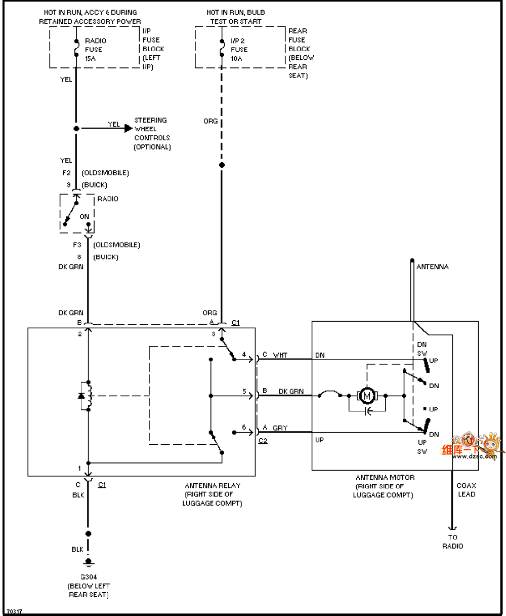
The Oldsmobile electric antenna circuit is shown below:

Power and ground
Power line: The line that connects the electric antenna to the vehicle power system (such as the battery) and is responsible for providing power to the electric antenna.
Ground line: A necessary connection to ensure the stable operation of the electric antenna system, usually connected to the metal structure of the vehicle body.
Control circuit
Control unit: It may be a body control module (BCM) or other dedicated control unit, which is responsible for receiving and processing input signals from switches, sensors, etc., and then controlling the action of the electric antenna.
Switch signal: A signal from the driver or an automatic control system (such as an automatic lifting system) that is used to trigger the lifting and lowering operation of the electric antenna.
Sensor signal (if applicable): Such as sensor signals used to detect the position and speed of the antenna, providing necessary feedback information to the control unit.
Electric antenna drive circuit
Motor driver: Converts the control signal sent by the control unit into executable instructions for the motor to drive the electric antenna to rise and fall.
Motor: The component that performs the actual lifting action, and realizes the lifting and lowering of the antenna by forward and reverse rotation.
Signal transmission and interface
If the electric antenna has signal receiving or transmitting functions (such as for vehicle communication or navigation), the corresponding signal transmission path and interface will be shown in the circuit diagram.
The interface may include connections with the radio, navigation system or other on-board equipment.
Wiring harness and connector
The circuit diagram will show in detail the type, specification and location of the wiring harness, cable and connector used in the electric antenna system.
Connectors may include plugs, sockets, terminals, etc., which are used to achieve electrical connections in the circuit.
Safety protection measures
The circuit diagram may contain safety protection components such as fuses and relays to prevent abnormal situations such as circuit overload and short circuit.
These protection components are usually located in key positions of power lines and control circuits.
Graphic symbols and codes
Specific graphic symbols will be used in the circuit diagram to represent various electrical components and connection relationships.
The codes of components and connectors will be used to identify their types and locations, which are convenient for quick positioning during maintenance and replacement.
Router Antenna, Patch Antenna, Wifi Antenna


